Electromagnetic coil
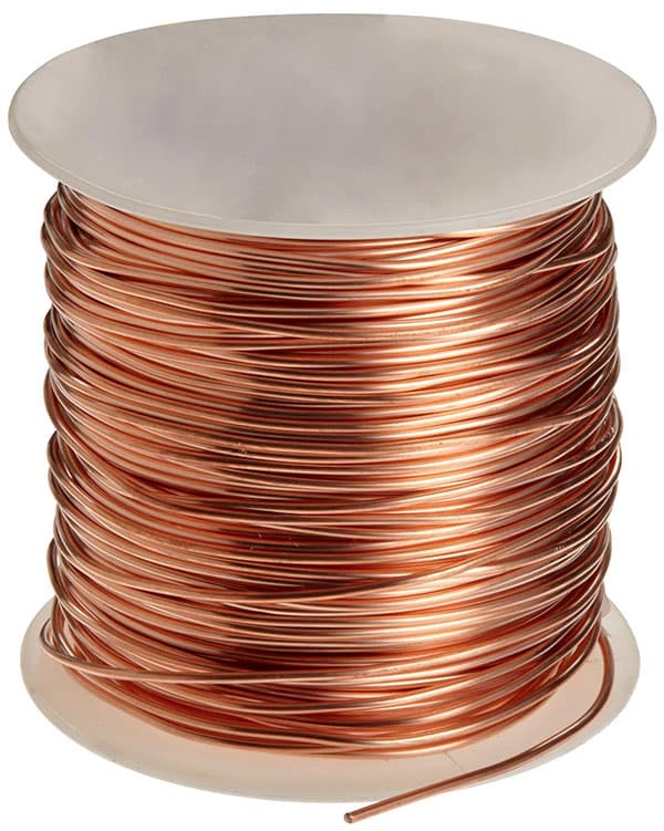
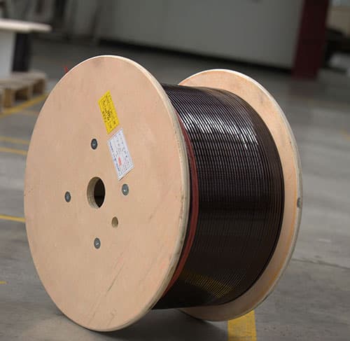
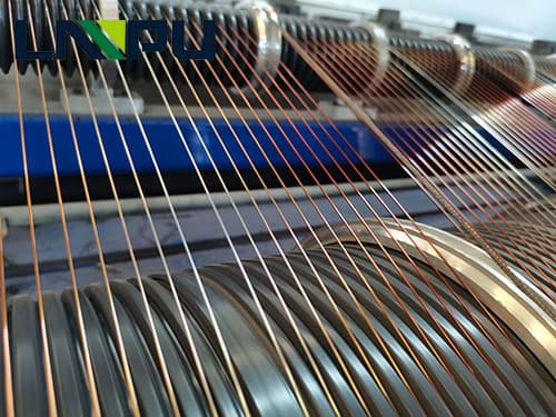
The coil is wound around an insulating tube by a wire, and the wires are insulated from each other. The insulating tube can be hollow, or it can contain an iron core or a magnetic powder core. The inductance of the coil is represented by L, and the units are Henry (H), millihenry (mH), microhenry (¦ÌH), 1H=10^3mH=10^6¦ÌH.
Inductance coil is a device that uses the principle of electromagnetic induction to work. When a current flows through a wire, a certain electromagnetic field will be generated around the wire, and the wire of the electromagnetic field itself will induce the wire in the range of the electromagnetic field. The effect on the wire itself that generates the electromagnetic field is called “self-inductance”, that is, the changing current generated by the wire itself produces a changing magnetic field, which further affects the current in the wire; the effect on other wires in the electromagnetic field range , Called “mutual inductance”.
The electrical characteristics of inductance coils are opposite to capacitors, “passing low frequencies and blocking high frequencies”. High-frequency signals will encounter great resistance when passing through the inductance coil, and it is difficult to pass; while the resistance presented by low-frequency signals passing through it is relatively small, that is, low-frequency signals can pass through it easily. The resistance of the inductor to direct current is almost zero.
Resistance, capacitance and inductance, they all present a certain resistance to the flow of electrical signals in the circuit, and this resistance is called “impedance”. The impedance presented by the inductor to the current signal uses the self-inductance of the coil. Inductance coil is sometimes referred to as “inductance” or “coil”, represented by the letter “L”. When winding an inductance coil, the number of turns of the coil is generally called the “number of turns” of the coil.
Classification
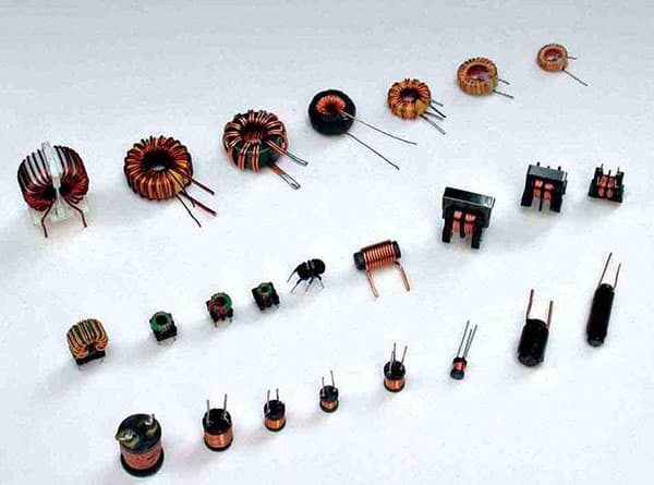
There are roughly the following categories of inductance coils commonly used in circuits:
Classified according to the form of inductance: fixed inductance, variable inductance.
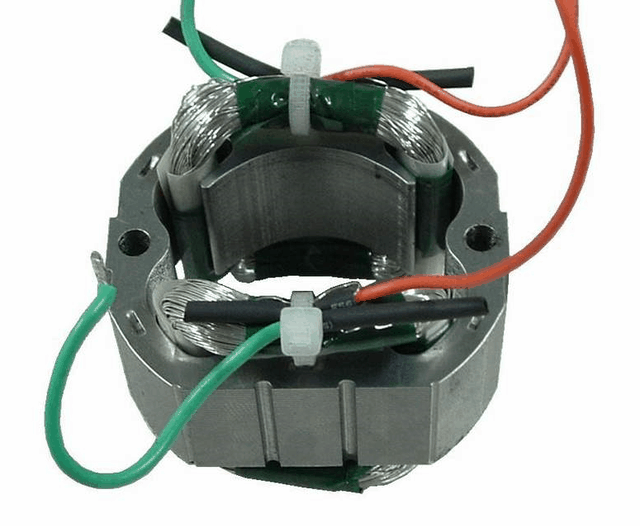
According to the nature of the magnetic conductor: air core coil, ferrite coil, iron core coil, copper core coil.
Classified by work nature: antenna coil, oscillating coil, choke coil, trap coil, deflection coil.
According to the winding structure classification: single-layer coil, multi-layer coil, honeycomb coil, close-wound coil, indirect wound coil, unborn coil, honeycomb coil, random winding coil.
Commonly used coils
1. Single layer coil
Single-layer coils are wound around a paper tube or bakelite frame with insulated wires. Such as the medium wave antenna coil of a transistor radio.
2. Honeycomb coil
If the plane of the coil being wound is not parallel to the rotating surface, but intersects at a certain angle, this kind of coil is called a honeycomb coil. The number of times the wire is bent back and forth after one rotation is often called the number of break points. The advantages of the honeycomb winding method are small size, small distributed capacitance, and large inductance. The honeycomb coils are all wound by the honeycomb winding machine, the more the turning points, the smaller the distributed capacitance
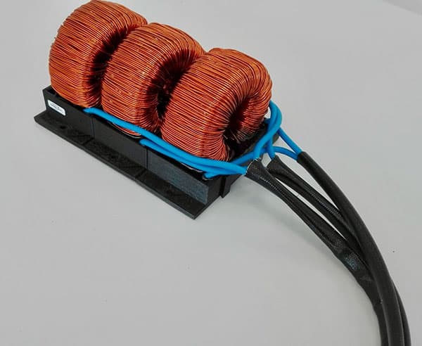
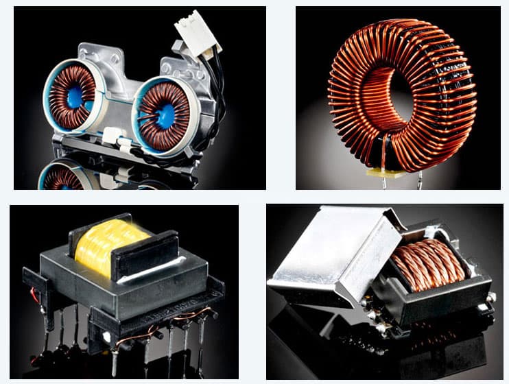
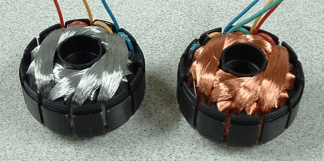
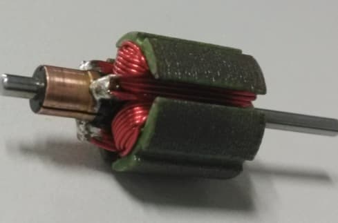
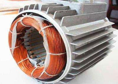
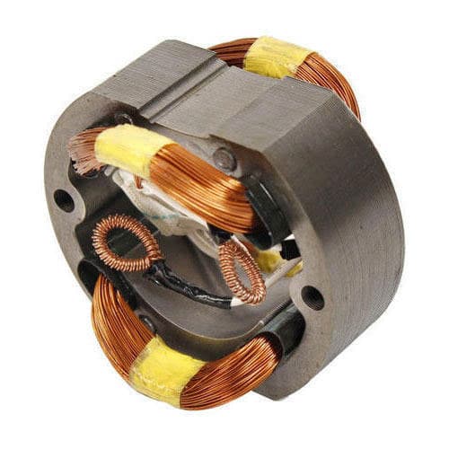
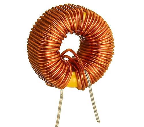
3. Ferrite core and iron powder core coil
The inductance of the coil is related to the presence or absence of a magnetic core. Inserting a ferrite core in the air-core coil can increase the inductance and improve the quality factor of the coil.
4. Copper core coil
Copper core coils are widely used in the ultrashort wave range. The position of the copper core in the coil is used to change the inductance. This adjustment is more convenient and durable.
5. Color code inductor
The color code inductor is an inductor with a fixed inductance, and its inductance marking method is the same as the resistance with a color ring.
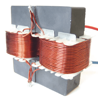
6. Choke coil (choke coil)
The coil that restricts the passage of alternating current is called a choke coil, which is divided into a high-frequency choke coil and a low-frequency choke coil.
7. Deflection coil
The deflection coil is the load of the output stage of the TV’s scanning circuit. The deflection coil requires: high deflection sensitivity, uniform magnetic field, high Q value, small size, and low price.